Gravio is a system for efficiently collecting and managing data from various types of sensors. This manual explains the basic procedures for collecting sensor data using Gravio.
The overall process for collecting sensor data in Gravio is as follows:
To use Zigbee-compatible devices, you need to connect a Zigbee USB receiver to your PC.
If the Zigbee USB receiver is not recognized on Windows or Mac, you need to install drivers from the Silicon Lab website:
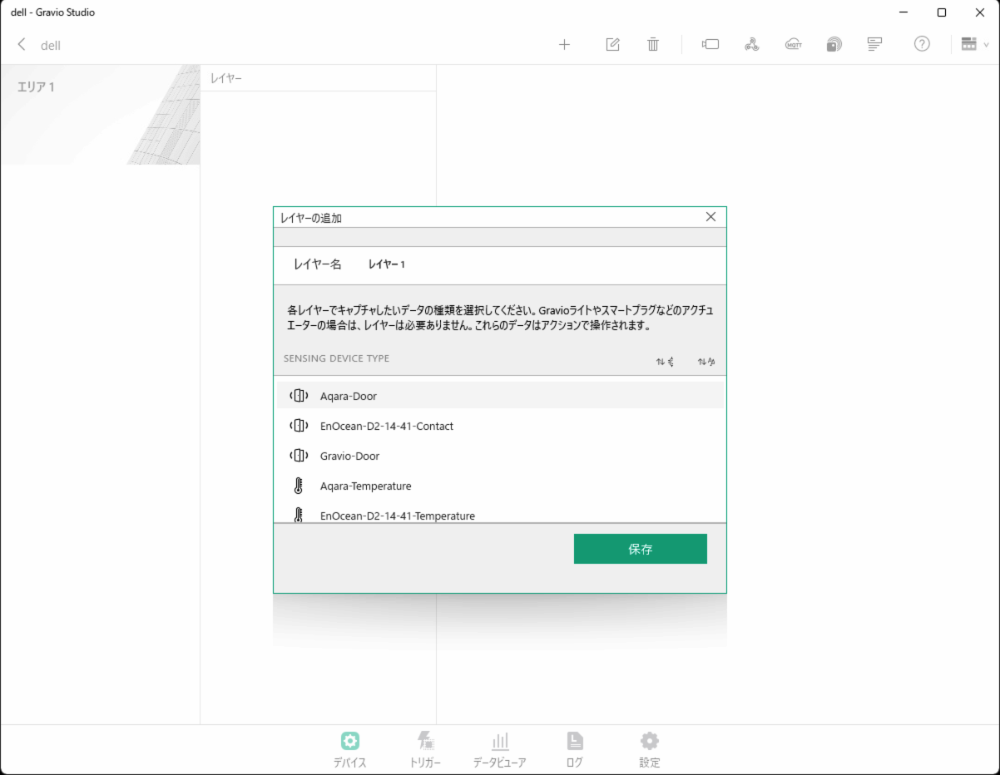
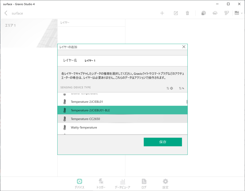
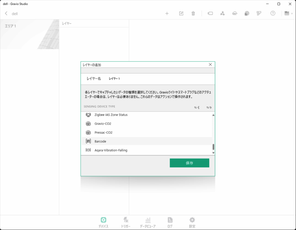
In the “Device” tab, select the type of Zigbee sensor (DataKind) to add a new area and layer.
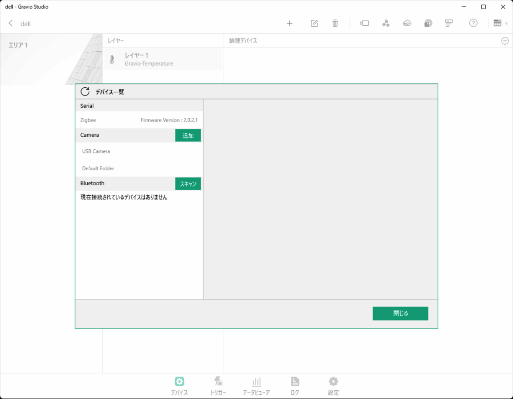
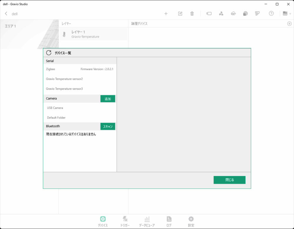
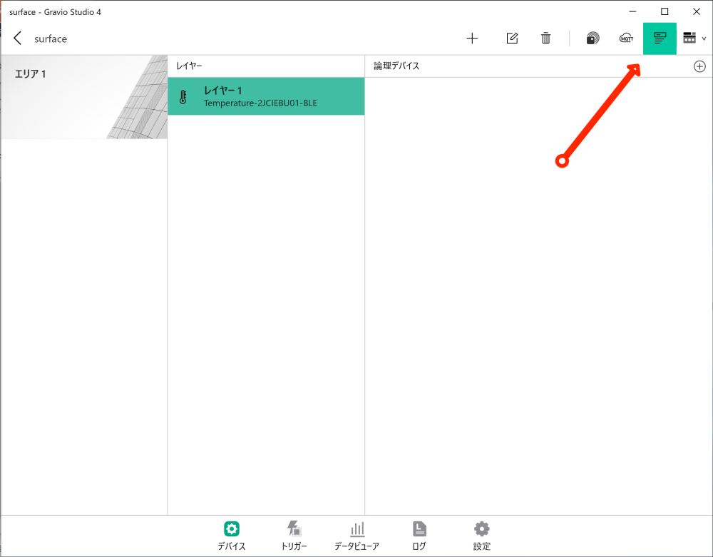
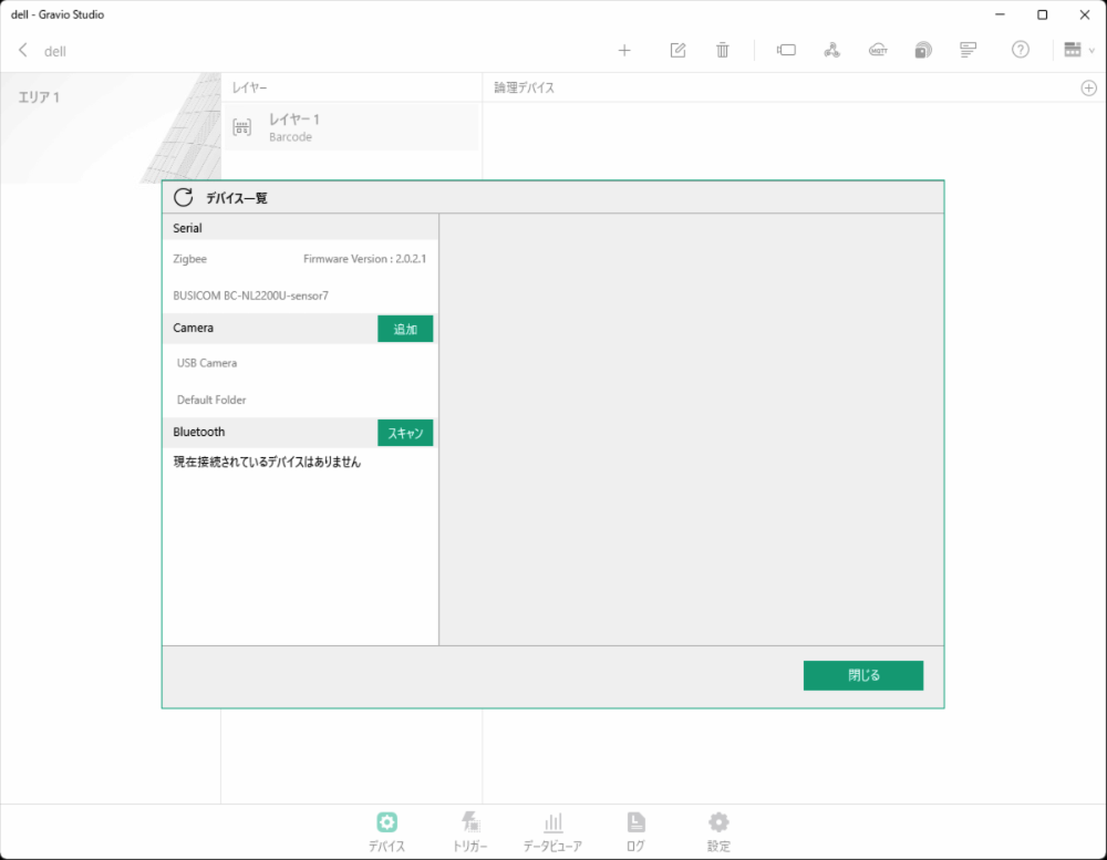
To receive sensor data from Zigbee-compatible devices, you first need to pair the sensor with the sensor receiver. Press the following button to display the sensor receiver settings screen connected to the serial port.

The device list screen will be displayed. Verify that the Zigbee USB receiver is properly connected.
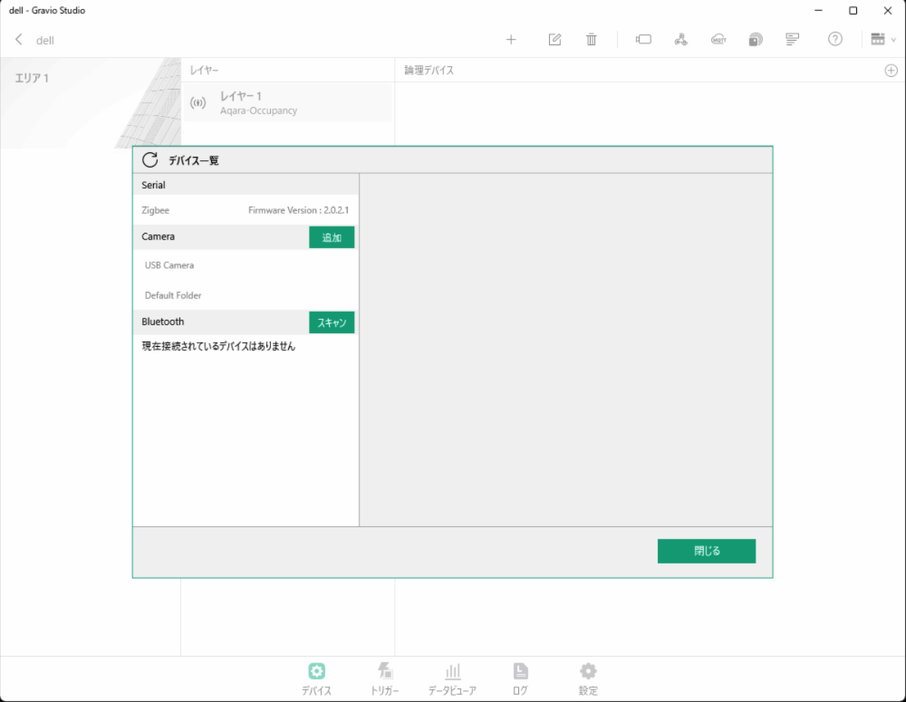
Press the “Pairing” button to put the receiver in pairing wait state. (Pairing mode lasts for 1 minute.)
When you press and hold the button on the sensor side for about 5 seconds during pairing mode, the sensor will be paired and displayed as follows.
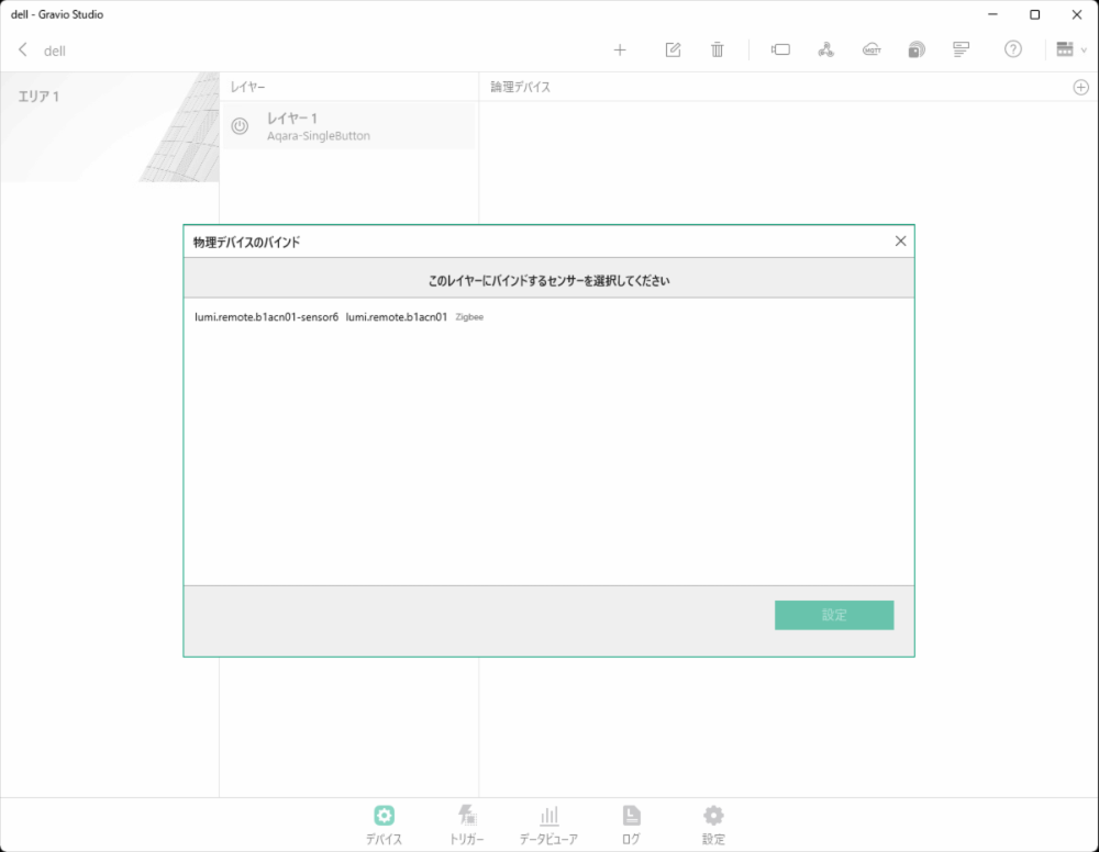
If “Automatically set if there are available layers during pairing” is enabled, and there is a layer configured for the paired device type, the device will be automatically registered to that layer and the settings will be activated.
Connect the EnOcean dedicated USB receiver to your PC.
Open the sensor receiver settings screen
Press the button on the EnOcean-compatible device After a while, the sensor will appear in the serial port
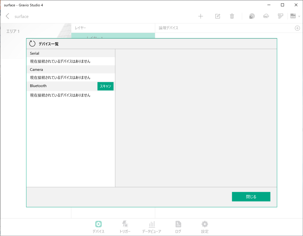
Use the PC’s built-in Bluetooth function or a Bluetooth USB receiver.
Open the sensor receiver settings screen
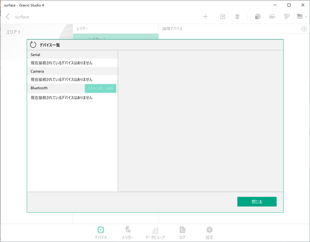
Click the right arrow on the Bluetooth line and press the scan button
Sensors will be displayed when discovered during scan mode
The detected device (in this example, Omron 2JCIE-BU01-sensor-1) is displayed
Gravio can use barcode readers (barcode readers with USB COM port emulation capability) as a layer for data input. Here, we explain the setup procedure for barcode readers using the BUSICOM BC-NL2200U as an example.
The barcode reader must be configured for USB COM port emulation functionality. Models such as BUSICOM’s BC-NL1100U, BC-NL1100U II, BC-NL2200U, BC-NL2200U II, BC-NL3000U, and BC-NL3000U III can switch between USB HID-KBW functionality and USB COM port emulation functionality. When using with Gravio, make sure to set it to USB COM port emulation functionality.
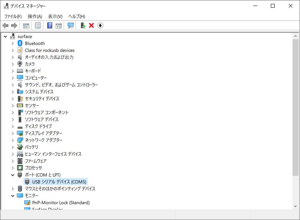
For Windows, you can verify the barcode reader connection in Device Manager
Verify that “USB Serial Device (COMx)” (e.g., COM5) appears under Ports (COM & LPT)

Note: If BUSICOM BC-NL2200U is not displayed, verify that the barcode reader is properly connected to the USB port and configured for USB COM port emulation functionality, then restart HubKit.
(GPS device setup procedures will be added in the future)
After completing physical device connection, set up the logical data structure in Gravio.
Areas represent the physical locations where devices are installed.
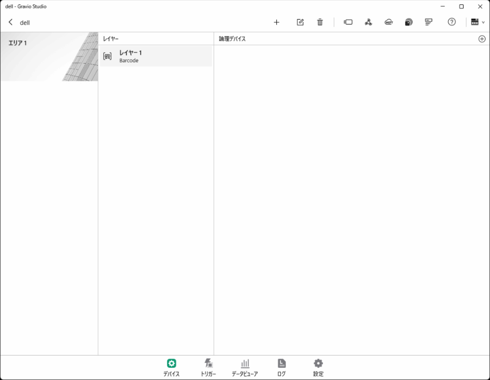
After creating an area, add layers within that area.
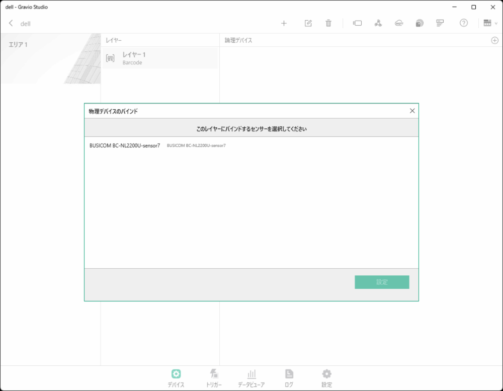
Add the physically connected and paired sensor devices to the created layers.
After sensor setup is complete, begin data reception.
If devices are not properly recognized:
If sensor data cannot be collected:
When Hub is installed, it creates a data directory for saving configuration files and data.
C:\ProgramData\HubKit
/Library/Application Support/HubKit/
Since it runs in Docker on Linux/Raspberry, the following directory is mounted as a volume:
/home/gravio/hubkitrepo4/data
Images obtained from cameras via ONVIF etc. are saved in directories organized by camera device and date in the following directory:
C:\ProgramData\HubKit\mediadata
/Library/Application Support/HubKit/mediadata
Since it runs in Docker on Linux/Raspberry, when viewed from the Host side, the following directory is mounted as a volume:
/home/gravio/hubkitrepo4/data/mediadata
When viewed from inside Docker, the directory is:
/var/opt/hubkit/mediadata