Description
The ModbusRTU Master component can communicate with Modbus RTU-compatible Slave devices through USB-serial adapters.
About Modbus Component Output
JSON array when physical device ID is specified:
[
   {
      "DeviceId": "cu.usbserial-OL111162",
      "ResponseData": [16,1,45626,1],
      "ResponseRaw": [1,3,8,0,16,0,1,178,58,0,1,127,99]
   }
]
JSON object when physical device ID is specified
{
  "DeviceId": "cu.usbserial-OL111162",
  "ResponseData": [16,1,45626,1],
   "ResponseRaw": [1,3,8,0,16,0,1,178,58,0,1,127,99]
}
Modbus Response Description
"DeviceId" is the physical device ID of the serial device.
"ResponseRaw" shows the raw response from the Modbus device,
"ResponseData" contains only the information of read or written data.
For "(0x01) Read Coils" and "(0x02) Read Discrete Inputs", the response is in bit format.
Example: "ResponseData": [0, 1, 0, 1, 0, 0, 0, 0, 1, 0, 0, 0, 1, 0, 0, 0] (length varies depending on command settings)
For "(0x03) Read Holding Registers" and "(0x04) Read Input Registers", the response is in 2-byte format.
Example: "ResponseData": [6, 20000] (length varies depending on command settings)
For "(0x05) Write Single Coil" and "(0x06) Write Single Register", a 2-byte response is returned containing the data address and written data.
Example: "ResponseData": [12, 65280] (12 = data address, 65280 = written data)
For "(0x0F) Write Multiple Coils" and "(0x10) Write Multiple Registers", a 2-byte response is also returned containing the first data address and the number of written coils or registers.
Example: "ResponseData": [5, 2] (5 = first data address, 2 = number of written coils or registers)
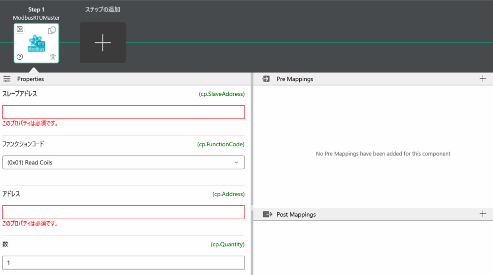
Component Properties
| Property Name | Description |
|---|---|
| Slave Address (SlaveAddress) | Specify the slave address of the device Can be entered in decimal and hexadecimal. For hexadecimal, add "0x" before the number |
| Function Code (FunctionCode) | Select supported function codes from the following list (0x01) Read Coils (0x02) Read Discrete Inputs (0x03) Read Holding Registers (0x04) Read Input Registers (0x05) Write Single Coil (0x06) Write Single Register (0x0F) Write Multiple Coils (0x10) Write Multiple Registers |
| Address | Specify the first register or coil to read or write |
| Quantity | This property is used only when the function code is "(0x01) Read Coils" "(0x02) Read Discrete Inputs" "(0x03) Read Holding Registers" "(0x04) Read Input Registers" "(0x0F) Write Multiple Coils" "(0x10) Write Multiple Registers" Specify the number of registers or coils to read or write according to the specified function code |
| Data | This property is used only when the function code is "(0x05) Write Single Coil" "(0x06) Write Single Register" "(0x0F) Write Multiple Coils" "(0x10) Write Multiple Registers" Specify the data to write here Can be entered in decimal and hexadecimal. For hexadecimal, add "0x" before the number Data must be entered comma-separated byte by byte. (Example: 0xFA, 224, 5, 0x4) |
| Physical Device ID | When nothing is set, data output is executed from all Modbus USB devices or USB-serial adapters When using multiple Modbus USB devices or USB-serial adapters, device IDs can be described comma-separated*1 |
※1 Note: When multiple different Modbus USB devices or USB-serial adapters are connected, if the device ID is not specified, the same command may be sent to different devices, which may cause errors.
The Physical Device ID can be omitted in the following cases:
- When only one Modbus physical device is connected
- When 2 or more Modbus physical devices are connected and all have the same slave address and same operation
Example: Multiple USB sensors are connected and data is collected together with the same command
Configuration file changes are required to connect to the device, so please contact us.