Gravio Device Manual
Table of Contents
- 1. Introduction
- 2. Overall Flow of Sensor Data Collection
- 3. Device Setup
- 3.1 Zigbee Devices
- 3.2 EnOcean Devices
- 3.3 Bluetooth Devices
- 3.4 Barcode Readers
- 3.5 GPS Devices
- 4. Data Structure Setup
- 4.1 Creating Areas
- 4.2 Adding Layers
- 4.3 Adding Sensors
- 5. Starting and Verifying Data Collection
- 6. Troubleshooting
- 7. Appendix
- 7.1 HubKit Data Directory
- 7.2 Camera Image Storage Location
1. Introduction
Gravio is a system for efficiently collecting and managing data from various types of sensors. This manual explains the basic procedures for collecting sensor data using Gravio.
2. Overall Flow of Sensor Data Collection
The overall process for collecting sensor data in Gravio is as follows:
- Physical Device Connection and Pairing - Physically connect sensor devices to HubKit and perform pairing as needed
- Logical Data Structure Setup - Define areas (physical locations) and layers (sensor types)
- Sensor Addition - Associate physical devices with the created layers
- Data Collection Start - Enable settings to begin data reception
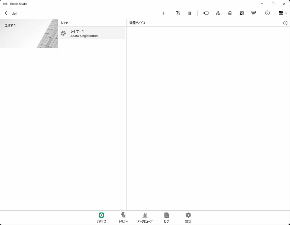
3. Device Setup
3.1 Zigbee Devices
Required Hardware
To use Zigbee-compatible devices, you need to connect a Zigbee USB receiver to your PC.
If the Zigbee USB receiver is not recognized on Windows or Mac, you need to install drivers from the Silicon Lab website: - For Windows: Download and install "CP210x Windows Drivers" - For Mac: Download and install "CP210x VCP Mac OSX Driver"
Zigbee Device Addition Procedure
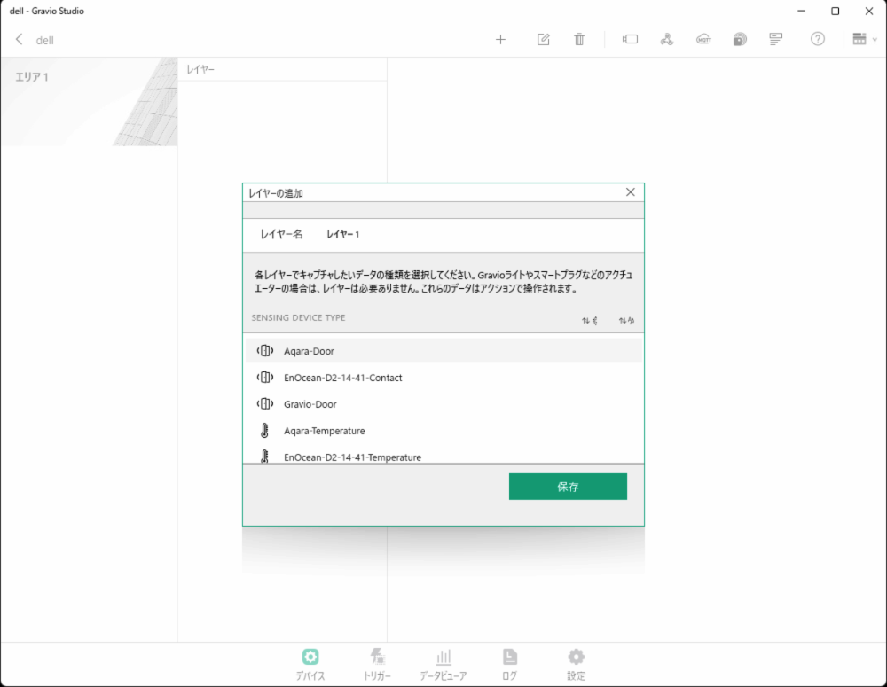
- In the "Device" tab, select the type of Zigbee sensor (DataKind) to add a new area and layer.
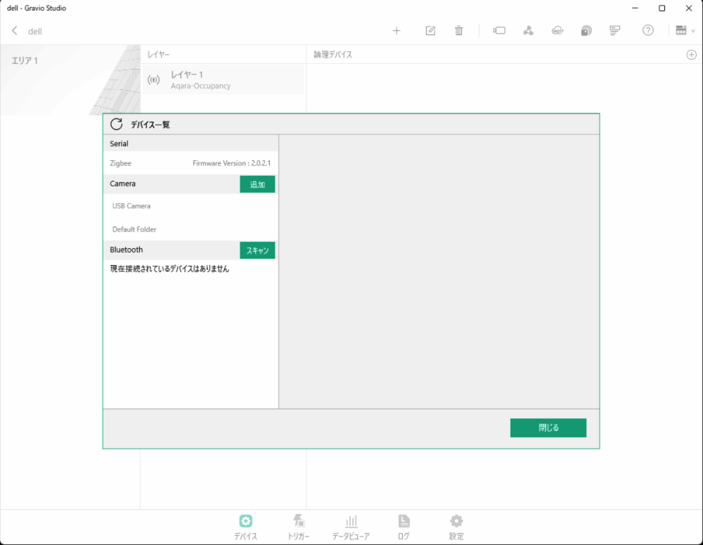
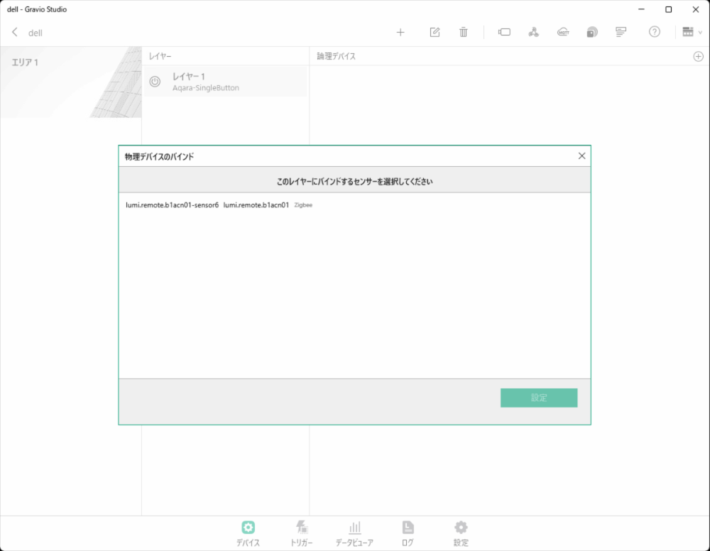
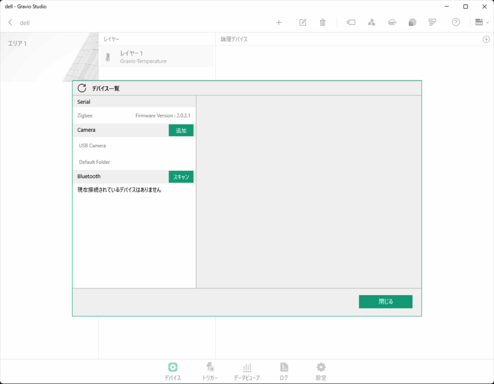
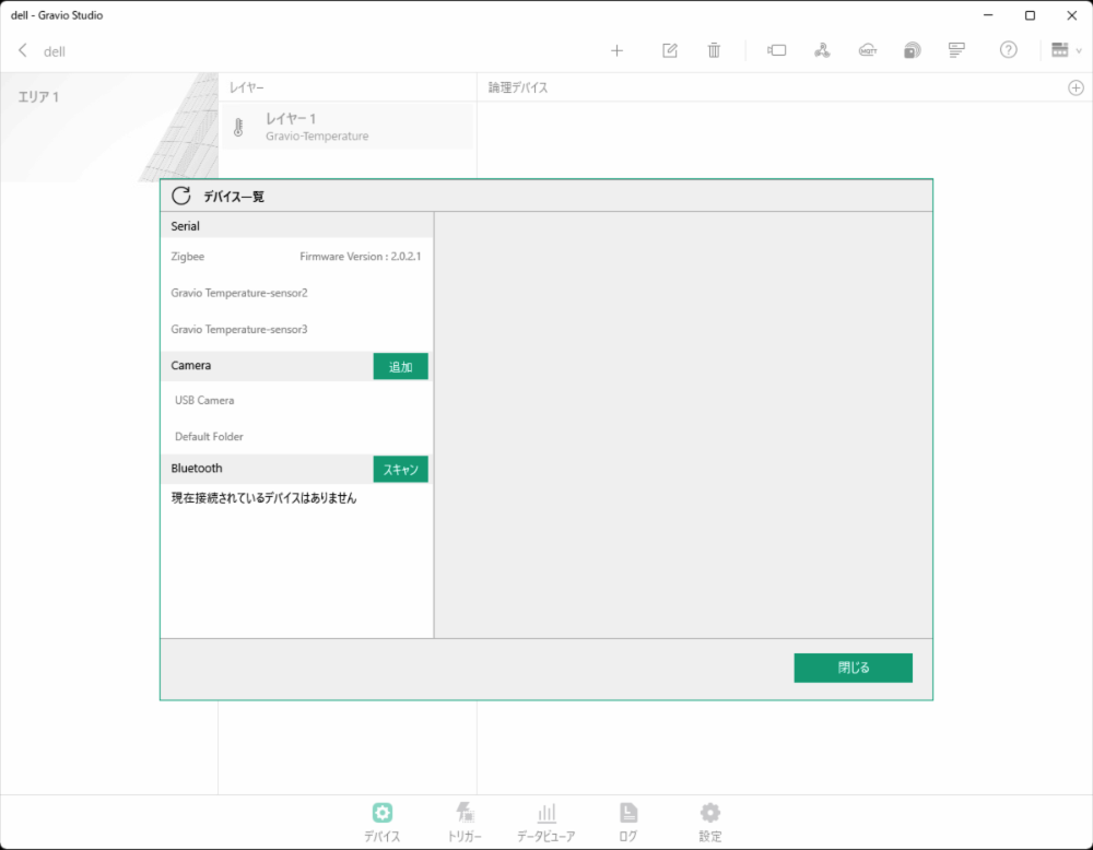
- To receive sensor data from Zigbee-compatible devices, you first need to pair the sensor with the sensor receiver. Press the following button to display the sensor receiver settings screen connected to the serial port.
- The device list screen will be displayed. Verify that the Zigbee USB receiver is properly connected.
Zigbee Device Pairing
- Press the "Pairing" button to put the receiver in pairing wait state. (Pairing mode lasts for 1 minute.)

- When you press and hold the button on the sensor side for about 5 seconds during pairing mode, the sensor will be paired and displayed as follows.
Data Reception Activation
If "Automatically set if there are available layers during pairing" is enabled, and there is a layer configured for the paired device type, the device will be automatically registered to that layer and the settings will be activated.
3.2 EnOcean Devices
EnOcean Required Hardware
Connect the EnOcean dedicated USB receiver to your PC.
EnOcean Device Addition Procedure
- Open the sensor receiver settings screen
- Press the button on the EnOcean-compatible device After a while, the sensor will appear in the serial port
3.3 Bluetooth Devices
Bluetooth Required Hardware
Use the PC's built-in Bluetooth function or a Bluetooth USB receiver.
Bluetooth Device Addition Procedure
- Open the sensor receiver settings screen

- Click the right arrow on the Bluetooth line and press the scan button
- Sensors will be displayed when discovered during scan mode

- The detected device (in this example, Omron 2JCIE-BU01-sensor-1) is displayed

3.4 Barcode Readers
Gravio can use barcode readers (barcode readers with USB COM port emulation capability) as a layer for data input. Here, we explain the setup procedure for barcode readers using the BUSICOM BC-NL2200U as an example.
Prerequisites
The barcode reader must be configured for USB COM port emulation functionality. Models such as BUSICOM's BC-NL1100U, BC-NL1100U II, BC-NL2200U, BC-NL2200U II, BC-NL3000U, and BC-NL3000U III can switch between USB HID-KBW functionality and USB COM port emulation functionality. When using with Gravio, make sure to set it to USB COM port emulation functionality.
Barcode Reader Connection Verification
- For Windows, you can verify the barcode reader connection in Device Manager
- Verify that "USB Serial Device (COMx)" (e.g., COM5) appears under Ports (COM & LPT)
Barcode Reader Addition Procedure
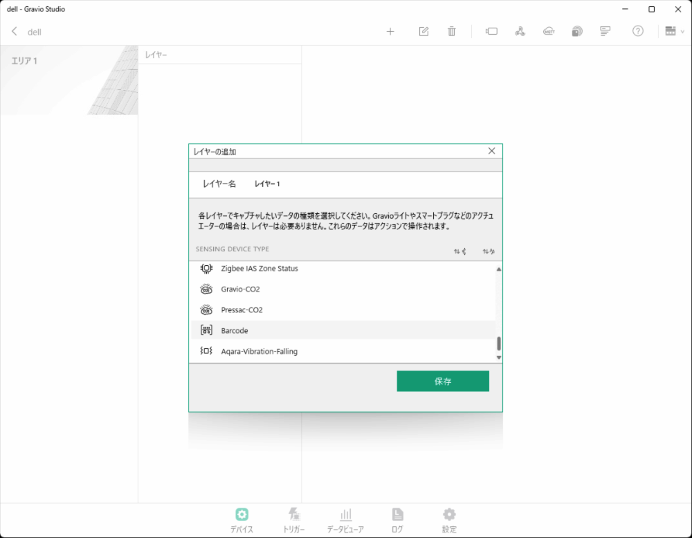
- Adding Area and Layer
- In "Device", select Barcode (DataKind) to add a new area and layer
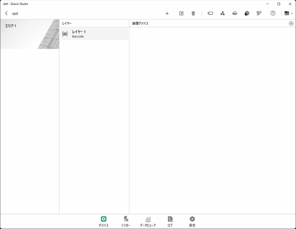
- Barcode Reader Setup
- Connect the barcode reader to the USB port
- Click the circled "+" mark in the top right of the screen
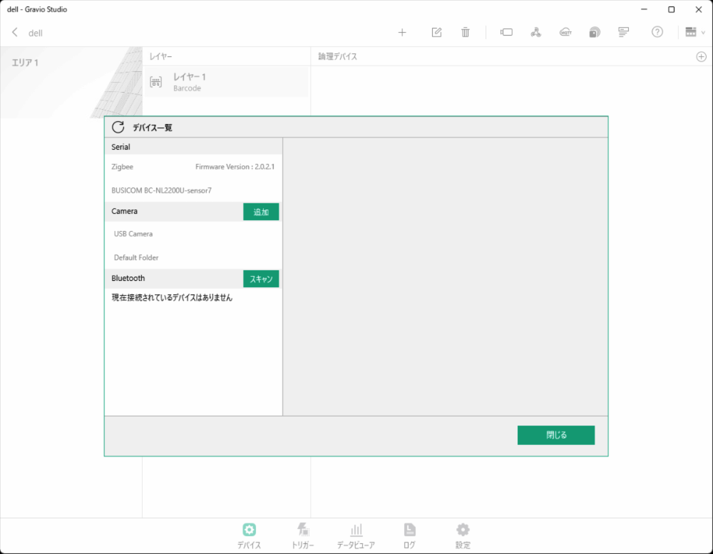
- Device List Verification
- The device list will be displayed
- Verify that BUSICOM BC-NL2200U is displayed

Note: If BUSICOM BC-NL2200U is not displayed, verify that the barcode reader is properly connected to the USB port and configured for USB COM port emulation functionality, then restart HubKit.
- Device and Layer Association
- Click the circled "+" mark in the top right of the window
- Select the barcode reader you want to connect to the layer

- Barcode Reader Activation
- After setup is complete, turn the switch ON to begin data reception

Notes
- When using BUSICOM barcode readers, USB COM port emulation functionality configuration is required. Please refer to the BUSICOM manual for details.
- If the barcode reader is not properly recognized, verify the connection and settings, then try restarting HubKit.
- A list of barcode readers verified to work with Gravio can be found in the official documentation.
3.5 GPS Devices
In Gravio, GPS devices (GPS devices available via COM port connection) can be used as data input devices as a single layer.
Confirming GPS Device Connection
For Windows 10, confirm that COMx (in this case COM5) is displayed in the Device Manager to verify the GPS device connection.
GPS Device Addition Procedure
In this example, we explain how to get GPS data using a VKLSVAN VK172 G-MOUSE USB GPS device.
- In "Devices," select the GPS (DataKind) you want to use and add a new area and layer.
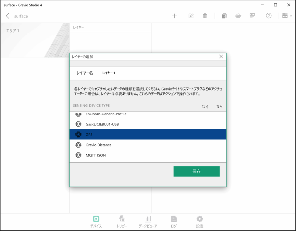
- To receive GPS data, connect the GPS device to a USB port, then press the following button to display the GPS device settings screen.
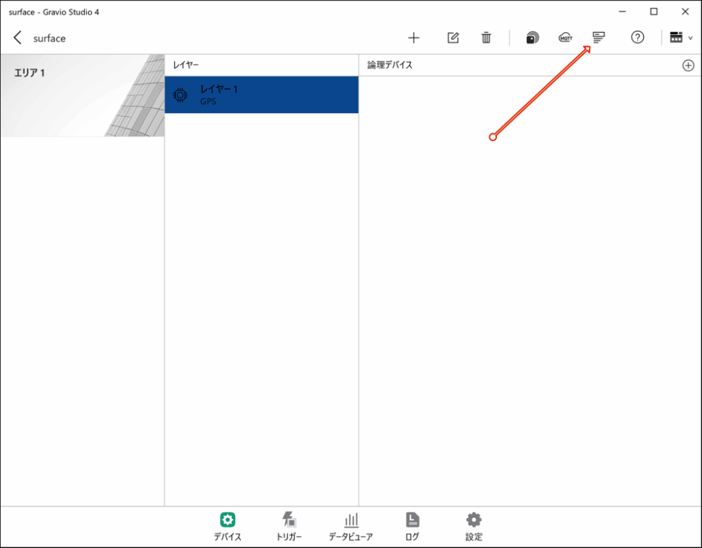
- The device list screen appears. Confirm that GPS Generic Type is displayed.
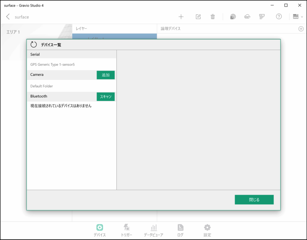
Note: If GPS Generic Type is not displayed, check that the GPS device is correctly connected to the USB port and restart HubKit.
If GPS Generic Type is displayed, you're done. Close the dialog.
- Next, click the circled "+" mark at the top right of the window.
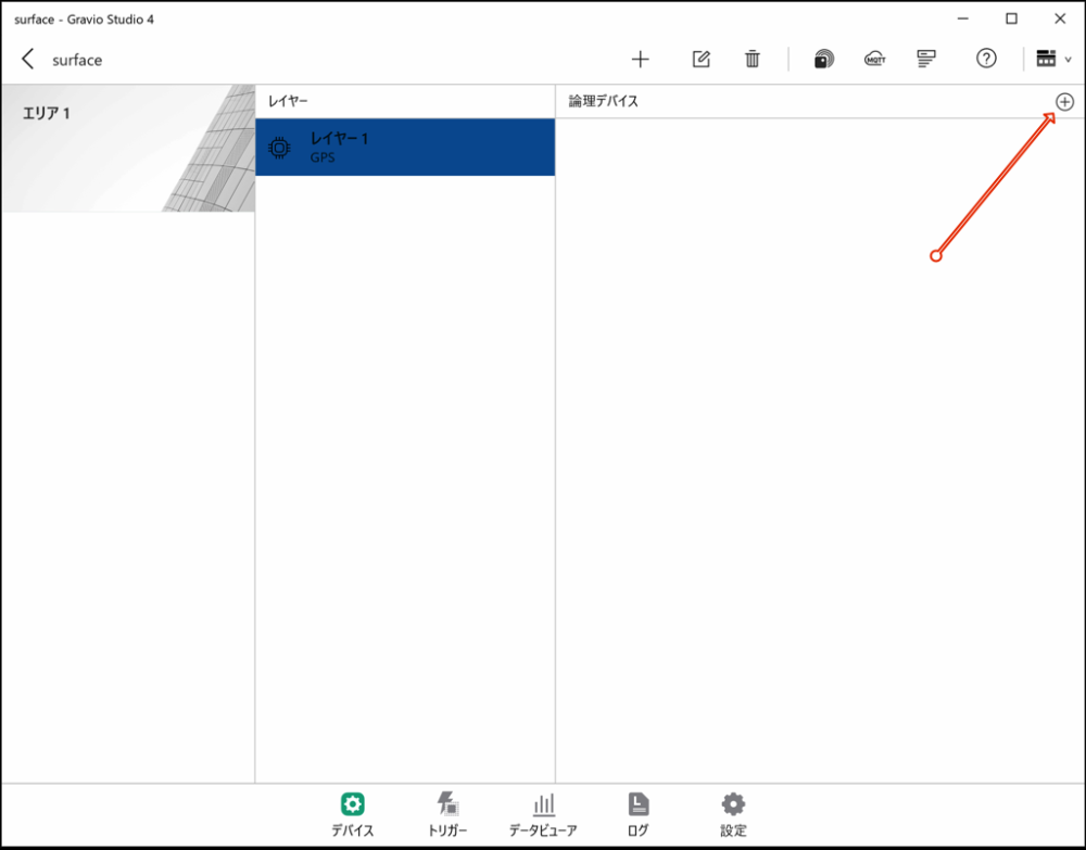
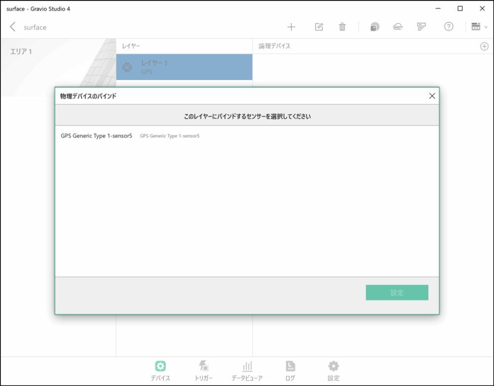
- Select and configure the GPS device you want to connect to the layer.
When you've finished configuring, close this screen.
- You will see a screen like the one below. Finally, turn ON the switch to receive data from this GPS device.
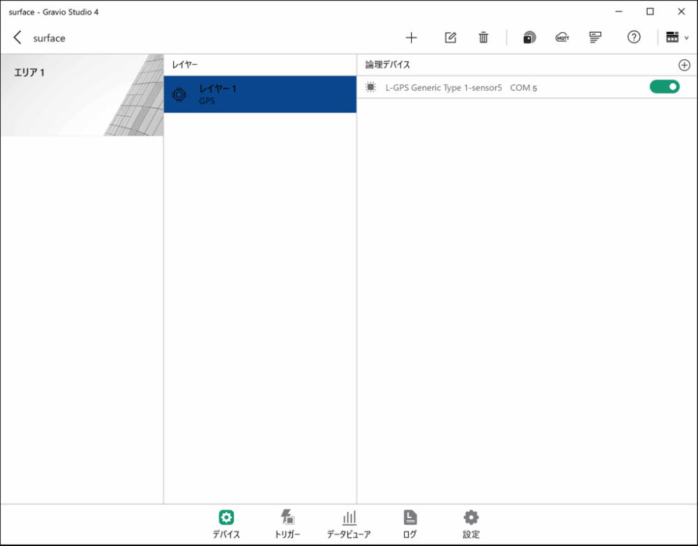
GPS data reception will start automatically from the GPS device.
GPS Data Format
The data that can be received from the GPS set in the layer is as follows. You can check it in the Data Viewer.
| Data | Description |
|---|---|
| Course | Device moving direction (value from 0 degrees north clockwise to 359.9 degrees) -1 if direction is invalid |
| SpeedKm | Device moving speed (km/h) |
| SpeedKn | Device moving speed (knots) |
| LatitudeDeg | Latitude (DEG format) |
| LongitudeDeg | Longitude (DEG format) |
| Latitude | Latitude (DMM format) |
| Longitude | Longitude (DMM format) |
| LatitudeDir | Latitude direction (N or S) |
| LongitudeDir | Longitude direction (E or W) |
Terminology: - DEG format: Data format ddd.ddd, where ddd.ddd is expressed in degrees with decimal point. This is the notation used in Google Maps. - DMM format: Data format dddmm.mmmm, where ddd is degrees and mm.mmmm is minutes in sexagesimal system, so 60 minutes equals 1 degree. The ddd.dddd degree notation used in Google Maps can be calculated as (degrees + minutes/60).
4. Data Structure Setup
After completing physical device connection, set up the logical data structure in Gravio.
4.1 Creating Areas
Areas represent the physical locations where devices are installed.
- Click the "+" mark in the top right of the Device tab to create a new area
- Name the area (e.g., "3rd Floor West", "Seminar Room", "Entrance Area", etc.)
- Adding photos can help with identification
4.2 Adding Layers
After creating an area, add layers within that area.
- Click "+" within the area to add a layer
- Give the layer a meaningful name (e.g., "Temperature Sensor Layer", "Motion Sensor Layer", etc.)
- Select the type of data (DataKind) to be collected in this layer
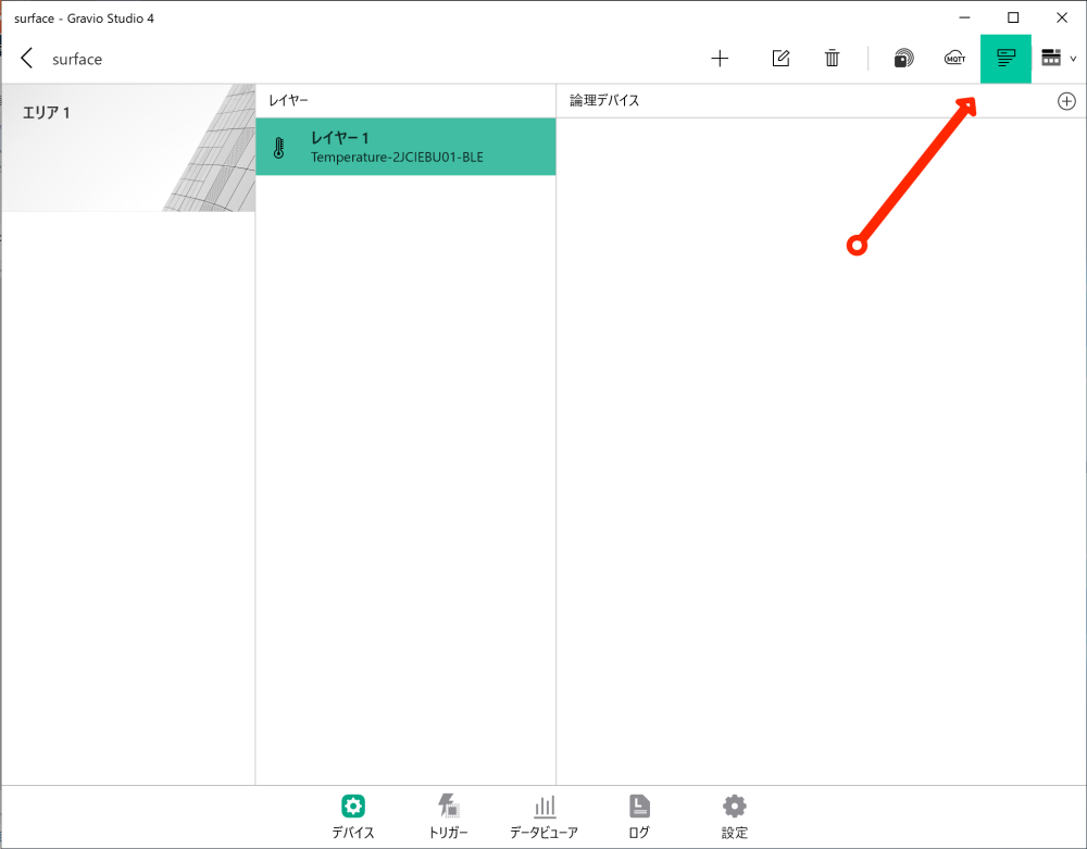
4.3 Adding Sensors
Add the physically connected and paired sensor devices to the created layers.
- Click the "+" mark in the top right of the sensor receiver settings screen
- Select and configure the sensor you want to connect to the layer
- Close the settings screen after configuration is complete
5. Starting and Verifying Data Collection
After sensor setup is complete, begin data reception.
- Turn ON the sensor receiver switch
- This will automatically begin data reception from the sensors
- For Zigbee, you can connect up to 64 devices with one dongle
- Use the data viewer to verify received data
6. Troubleshooting
If devices are not properly recognized:
- Verify that USB devices are properly connected
- Try changing the USB port
- Verify that device drivers are properly installed
- Restart HubKit
- For barcode readers and other COM port devices, verify they are configured for USB COM port emulation functionality
If sensor data cannot be collected:
- Verify that the receiver switch is ON
- Check if the distance between sensor and receiver is appropriate
- Check sensor battery level
- Verify layer settings are correct
- Check if the sensor is not registered in duplicate in another area/layer
7. Appendix
7.1 HubKit Data Directory
When Hub is installed, it creates a data directory for saving configuration files and data.
When Installed on Windows 10
C:\ProgramData\HubKit
When Installed on macOS
/Library/Application Support/HubKit/
When Installed on Linux/Raspberry
Since it runs in Docker on Linux/Raspberry, the following directory is mounted as a volume:
/home/gravio/hubkitrepo4/data
7.2 Camera Image Storage Location
Images obtained from cameras via ONVIF etc. are saved in directories organized by camera device and date in the following directory:
Windows 10
C:\ProgramData\HubKit\mediadata
macOS
/Library/Application Support/HubKit/mediadata
Linux/Raspberry
Since it runs in Docker on Linux/Raspberry, when viewed from the Host side, the following directory is mounted as a volume:
/home/gravio/hubkitrepo4/data/mediadata
When viewed from inside Docker, the directory is:
/var/opt/hubkit/mediadata